This product is not available for new orders. We recommend ordering: SR05-L.

| Services Available | |
|---|---|
| Repair | Yes |
| Calibration | Yes |
| Free Support | Yes |
Overview
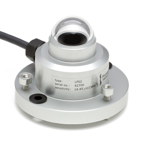
The LP02, manufactured by Hukseflux, is an ISO 9060:2018 spectrally flat Class C (second class) pyranometer that monitors solar radiation for the full solar spectrum range. It produces a millivolt signal that is measured directly by a Campbell Scientific data logger. The LP02 can provide solar radiation measurements for a variety of meteorological applications.
Read MoreBenefits and Features
- Compatible with most Campbell Scientific data loggers
- Measures reflected solar radiation when inverted
- Provides measurements in direct sunlight, under plant canopies, when the sky is cloudy, and in artificial light
- Includes bubble level and leveling screws, eliminating the need for a separate leveling base and simplifying installation
- Acceptable for providing the solar radiation data used in stability estimations
- Dome protects thermopile and allows water to roll off of it
- Designed for continuous indoor and outdoor use
Images


Detailed Description
The LP02 measures solar radiation with a high-quality blackened thermopile protected by a dome. The blackened thermopile provides a flat spectral response for the full solar spectrum range, which enables the LP02 to be used under plant canopies or lamps, when the sky is cloudy, and for reflected radiation measurements.
The LP02 includes a bubble level, three adjusting screws, and a cable gland. The bubble level and adjusting screws allow the sensor to be leveled without using a leveling base. The gland facilitates cable replacement.
The LP02 produces a millivolt signal that is measured directly by a Campbell Scientific data logger.
Two LP02 pyranometers can be mounted back-to-back to make a low-cost albedometer. Contact Campbell Scientific for more information.
Because the LP02 is a second-class pyranometer, it is acceptable for providing the solar radiation data used in stability estimations (EPA Meteorological Monitoring Guidance for Regulatory Modeling Applications, pages 2-10).
Compatibility
Note: The following shows notable compatibility information. It is not a comprehensive list of all compatible or incompatible products.
Data Loggers
| Product | Compatible | Note |
|---|---|---|
| 21X (retired) | ||
| CR10 (retired) | ||
| CR1000 (retired) | ||
| CR10X (retired) | ||
| CR200X (retired) | ||
| CR206X (retired) | ||
| CR211X (retired) | ||
| CR216X (retired) | ||
| CR23X (retired) | ||
| CR295X (retired) | ||
| CR300 (retired) | ||
| CR3000 (retired) | ||
| CR310 | ||
| CR500 (retired) | ||
| CR5000 (retired) | ||
| CR510 (retired) | ||
| CR6 | ||
| CR800 (retired) | ||
| CR850 (retired) | ||
| CR9000 (retired) | ||
| CR9000X (retired) |
Additional Compatibility Information
Mounting
The LP02 includes a bubble level and three adjusting leveling screws, which allow the sensor to be leveled without using a leveling base. The CM225 Solar Sensor Mounting Stand is used to attach the sensor to a crossarm. The CM225 consists of a rectangular plate, mounting bracket, U-bolts, washers, lock washers, and nuts. The LP02 should be mounted away from all obstructions and reflective surfaces that might adversely affect the measurement.
If the sensor needs to be mounted at an angle, a CM255 or CM255LS adjustable-angle mount can be used instead.
Specifications
| Sensor | Blackened thermopile protected by a dome |
| Measurement Description | Monitors solar radiation for the full solar spectrum range |
| Spectral Range | 285 to 3000 nm |
| Maximum Irradiance | 2000 W/m2 |
| Sensitivity | 15 µV/W/m2 (nominal) |
| Operating Temperature Range | -40° to +80°C |
| Temperature Dependence | < 0.15% per °C |
| ISO Classification | ISO 9060:2018 spectrally flat Class C (second class) |
| Body Diameter | 7.8 cm (3.1 in.) |
| Dome Diameter | 3.0 cm (1.2 in.) |
| Height | 5.9 cm (2.3 in.) |
| Weight | 363 g (0.8 lb) with 4.6 m (15 ft) cable |
Documents
Brochures
Manuals
Frequently Asked Questions
Number of FAQs related to LP02-L: 12
Expand AllCollapse All
-
Yes. It is recommended to clean the dome weekly. However, depending on the environment the pyranometer is deployed in, it may need to be cleaned more frequently—perhaps daily. The frequency of the cleaning schedule varies based on the amount of buildup on the dome caused by precipitation, dust, and biological films.
-
The LP02-L produces an analog millivolt signal that is linearly related to the amount of solar radiation incident on the device. This relationship is based on a calibration coefficient that is entered in the data logger program.
-
Yes. Depending on the application, it is recommended to have the sensor calibrated every one to two years.
-
Perhaps, but it is more likely that there is a wiring or programming issue. If the pyranometer is reading 0 W/m2, separate it from the data logger and measure the resistance across the sensor leads. If the reading is approximately 0 ohms, the sensor has likely been damaged and will need to be repaired or replaced. For information about the process of returning equipment to Campbell Scientific, refer to the Repair and Calibration page.
-
The LP02-L measures solar irradiance with primary units of W/m2 and over a range of 0 to ≈1000 W/m2 for terrestrial radiation. Other units can be measured with modifications to the measurement instruction in the data logger’s program.
-
Most Campbell Scientific sensors are available as an –L, which indicates a user-specified cable length. If a sensor is listed as an –LX model (where “X” is some other character), that sensor’s cable has a user-specified length, but it terminates with a specific connector for a unique system:
- An –LC model has a user-specified cable length for connection to an ET107, CS110, or retired Metdata1.
- An –LQ model has a user-specified cable length for connection to a RAWS-P weather station.
If a sensor does not have an –L or other –LX designation after the main model number, the sensor has a set cable length. The cable length is listed at the end of the Description field in the product’s Ordering information. For example, the 034B-ET model has a description of “Met One Wind Set for ET Station, 67 inch Cable.” Products with a set cable length terminate, as a default, with pigtails.
If a cable terminates with a special connector for a unique system, the end of the model number designates which system. For example, the 034B-ET model designates the sensor as a 034B for an ET107 system.
- –ET models terminate with the connector for an ET107 weather station.
- –ETM models terminate with the connector for an ET107 weather station, but they also include a special system mounting, which is often convenient when purchasing a replacement part.
- –QD models terminate with the connector for a RAWS-F Quick Deployment Station.
- –PW models terminate with the connector for a PWENC or pre-wired system.
-
Not every sensor has different cable termination options. The options available for a particular sensor can be checked by looking in two places in the Ordering information area of the sensor product page:
- Model number
- Cable Termination Options list
If a sensor is offered in an –ET, –ETM, –LC, –LQ, or –QD version, that option’s availability is reflected in the sensor model number. For example, the 034B is offered as the 034B-ET, 034B-ETM, 034B-LC, 034B-LQ, and 034B-QD.
All of the other cable termination options, if available, are listed on the Ordering information area of the sensor product page under “Cable Termination Options.” For example, the 034B-L Wind Set is offered with the –CWS, –PT, and –PW options, as shown in the Ordering information area of the 034B-L product page.
Note: As newer products are added to our inventory, typically, we will list multiple cable termination options under a single sensor model rather than creating multiple model numbers. For example, the HC2S3-L has a –C cable termination option for connecting it to a CS110 instead of offering an HC2S3-LC model.
-
For best results, use a differential voltage instruction, such as VoltDiff(). A single-ended voltage instruction, VoltSe(), could be used; however, this would not take full advantage of input reversal, which allows for the subtraction in common-mode gain errors. For more information, see the “The Benefits of Input Reversal and Excitation Reversal for Voltage Measurements” white paper.
-
Because of the loss of IR radiation, nearly all thermopile instruments typically have a negative offset. This offset is most easily visible at night-time, when a small negative value is read instead of zero. This same offset is present during the daytime, but it is not as visible because of the large solar signal.
Another common issue involves leveling an instrument. Leveling a thermopile instrument can cause errors in the direct beam component because the cosine response is not correct. These errors are more notable when the sun is close to the horizon because the angle is so shallow.
-
Many Campbell Scientific sensors are available with different cable termination options. These options include the following:
- The –PT (–PT w/Tinned Wires) option is the default option and does not display on the product line as the other options do. The cable terminates in pigtails that connect directly to a data logger.
- In the –C (–C w/ET/CS110 Connector) option, the cable terminates in a connector that attaches to a CS110 Electric Field Meter or an ET-series weather station.
- In the –CWS (–CWS w/CWS900 Connector) option, the cable terminates in a connector that attaches to a CWS900-series interface. Connection to a CWS900-series interface allows the sensor to be used in a wireless sensor network.
- In the –PW (–PW w/Pre-Wire Connector) option, the cable terminates in a connector that attaches to a prewired enclosure.
- In the –RQ (–RQ w/RAWS Connector) option, the cable terminates in a connector that attaches to a RAWS-P Permanent Remote Automated Weather Station.
Note: The availability of cable termination options varies by sensor. For example, sensors may have none, two, or several options to choose from. If a desired option is not listed for a specific sensor, contact Campbell Scientific for assistance.
Case Studies
Pont del Petroli was built in the 1960s to enable the transfer of oil from......read more
Privacy Policy Update
We've updated our privacy policy. Learn More
Cookie Consent
Update your cookie preferences. Update Cookie Preferences


