Overview
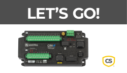
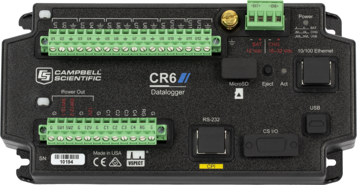
The CR6 Automated Monitoring Platform, designed on decades of infrastructure and environmental monitoring experience, is used by some of the largest monitoring networks worldwide. With the unique ability to serve both as an edge device and gateway, this simplifies networks that would otherwise require discrete devices to provide complete access to your data.
This unique platform is used where reliability, flexibility, and compatibility are essential to your success. The CR6 ecosystem supports an array of powerful peripherals that add channel capacity, distributed measurements, and communication capabilities, as well as measure vibrating wire sensors dynamically.
Campbell Scientific’s vibrating wire measurement devices, including the CR6, are the only devices that use patented VSPECT® technology. VSPECT filters external noise from your sensor and gives you diagnostic information about the quality of your vibrating wire measurement.
Learn about our patented VSPECT at our VSPECT® Essentials web resource.
The dynamic vibrating wire measurement technique is protected under U.S. Patent No. 8,671,758, and the vibrating wire spectral-analysis technology (VSPECT) is protected under U.S. Patent No. 7,779,690.
Read MoreBenefits and Features
- All-in-one edge device and gateway with built-in connectivity
- Native vibrating wire measurements using VSPECT
- Integrated communication options, charge regulator, and expandable storage to provide simplicity and reduced costs
- Configurable Universal (U) measurement and control terminals to measure virtually any sensor or application
- Availability of Campbell Scientific qualified support staff
- Designed and manufactured for long-term operation in extreme environments
Images


Similar Products
Detailed Description
The CR6 is the only monitoring platform currently available that operates as an edge device and gateway with connectivity, provides an industry standard for rugged design, has universal sensor compatibility and communication options, and includes VSPECT for vibrating wire measurements.
Edge and Gateway Device
The variability and site-specific challenges and constraints that exist in robust monitoring networks typically result in a wide array of devices to achieve full functionality. With built-in and modular measurement, processing, control, and communication capabilities, the CR6 is the only device that is needed.
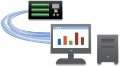
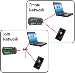
As a gateway device, the CR6 converts the data measured into the format or protocol required to seamlessly communicate on your network—whether on your computer or the cloud. Entry into the network does not require a separate edge device, as the CR6 also fills this role. Additionally, the CR6 forms a network as a connectivity device via spread-spectrum radio, Wi-Fi, serial, and RS-485.
Using the CR6 as an edge device and gateway with connectivity allows you to standardize on a single platform in your monitoring program. This simplifies purchasing, inventory management, and an overall required knowledge base. The CR6 is capable of a wide range of over thirty-five M2M protocols that include PakBus, MQTT, DNP3, IPv4, IPv6, HTTP/HTTPS, and PPP. Connectivity options include cellular, radio, satellite, Ethernet, and Wi-Fi. These communication methods enable access to critical data and the ability to receive alarms triggered by user-configured thresholds and events.
Native Vibrating Wire Using VSPECT
VSPECT, Campbell Scientific’s patented technology for measuring vibrating wire sensors, significantly improves vibrating wire sensor measurements—regardless of the manufacturer of the sensor. For more details about this unique technology visit our VSPECT® Essentials web resource.
Integrated Benefits for Simplicity and Reduced Costs
The integrated benefits and capabilities of the CR6 make it the most flexible platform available. In addition to several spread-spectrum radio options that are compatible with available frequencies across the world, it also includes Wi-Fi, Ethernet, and compatibility with modular cellular and satellite modems. Using Campbell Scientific communication peripherals ensures complete compatibility and extremely low power consumption.
The built-in charge regulator, with direct connections for main power or solar panels, is used to keep your battery charged. An intelligently designed and maintained power supply ensures long-term functionality and helps to capture data from critical events when you need it.
With regular data collection intervals or remote access, the 4 MB of onboard CR6 memory will likely be sufficient. However, if your application requires high measurement frequency; long, unattended deployments; or data storage redundancy, the CR6 has built-in expandable memory via a microSD card.
Communication Options
The CR6 Automated Monitoring Platform is available in different integrated communications frequency radio options.
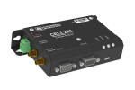
CR6-WIFI
The CR6-WIFI comes factory-configured as a Wi-Fi access point. Alternatively, the CR6-WIFI can be configured to join an existing Wi-Fi network with standard or Enterprise (EAP) security.
CR6-RF407
This 900 MHz, 250 mW, frequency-hopping spread-spectrum radio option can join a high-speed “mesh topology” radio network of other CR6s, ideal for medium-range, license-free radio communications.
CR6-RF412
Designed primarily for unlicensed operation in Australia and New Zealand, this 922 GHz, 250 mW, frequency-hopping spread-spectrum radio can join a high-speed “mesh topology” radio network of other CR6s and is also ideal for medium-range, license-free radio communications.
CR6-RF422
Used in the UK and EU and ideal for short- to medium-range, license-free radio communications, this 868 MHz, 25 mW option includes listen-before-talk (LBT) and adaptive-frequency-agility (AFA). It can join a high-speed “mesh topology” radio network of other CR6s using the included RF422 radio.
CR6-RF452
With this internal 900 MHz, 1 W, frequency-hopping spread-spectrum radio option, the CR6-RF452 can be part of a “star topology” network where all radio-frequency (RF) traffic routes back through the gateway. This option is ideal for long-range, license-free radio communications.
Universal Measurement and Control Terminals
The Universal or “U” terminals allow each terminal to be configured to measure a multitude of different types of sensor outputs. This allows the CR6 to be used in many different applications, regardless of the sensor types required—analog, digital, smart, or vibrating wire. This nearly limitless array of sensors includes inclinometers, meteorologic, hydrologic, piezometers, water quality, etc. The flexibility of Universal channels allows you to standardize on a single monitoring platform for all projects.
Support Staff
Recognized for more than 45 years for our outstanding customer support, Campbell Scientific includes experienced product engineering teams, knowledgeable technical support, attentive sales staff, and market-focused professionals who are committed to ensuring your success throughout the lifetime of your project.
Rugged Design
Unique to all CR6 Automated Monitoring Platforms is the design and manufacturing process used to ensure operational integrity in the most extreme environments. Each CR6:
- Includes surge electrostatic discharge (ESD) and over voltage protection, as well as dust protection.
- Is fully tested for shock and vibration tolerance.
- Is factory chamber tested for its full operational temperature range (standard range -40° to +70°C and extended range -55° to +85°C).
- Has been proven in hundreds of real-world applications.
These extreme measures are required to manufacture a product with a meantime between failure (MTBF) of 557 years! This means that if you purchase a CR6 today, your probability of failures during the warranty period (three years) is 0.6%. The CR6 Automated Monitoring Platform will last the entirety of your project, even if that means decades.
Compatibility
Note: The following shows notable compatibility information. It is not a comprehensive list of all compatible or incompatible products.
Software
| Product | Compatible | Note |
|---|---|---|
| DevConfig | (Version 2.10 or higher) | |
| LoggerLink | (Version 1.3 or higher) | |
| LoggerNet | (Version 4.3 or higher) | |
| LoggerNet Mobile Connect | (Version 1.0 or higher) | |
| PC400 | (Version 4.3 or higher) | |
| RTDAQ | (Version 1.2 or higher) | |
| Short Cut | (Version 3.1 or higher) |
Additional Compatibility Information
Sensors
With several terminal types, the CR6 is compatible with nearly every available sensor, including analog (both voltage and current), thermocouples, serial, SDI-12, vibrating wire, pulse, and frequency sensors.
Measurement and Control Peripherals
The CR6 is compatible with all CDMs, multiplexers, vibrating wire interfaces, terminal input modules, and relays.
Communications
The CR6 communicates with a PC via direct USB port, 10/100baseT Ethernet port, Wi-Fi, multidrop modems, short-haul modems, phone modems (land-line, digital cellular, and voice-synthesized), RF telemetry, and satellite transmitters (HDR GOES, Argos, Meteosat, Iridium, and Inmarsat).
Data can be viewed on an iOS or Android device.
| Data Logger Option | Radio Type | Integrated Radio Is Over-the-Air Compatible With |
|
CR6-WIFI |
2.4 GHz, 20 MHz bandwidth |
Most other Wi-Fi devices, such as the CR310-WIFI, CR300-WIFI, CR350-WIFI, NL241 |
|
CR6-RF407 |
902 to 928 MHz Frequency Hopping Spread Spectrum |
RF407, CR300-RF407, CRVW3-RF407, CR350-RF407 |
|
CR6-RF412 |
915 to 928 MHz Frequency Hopping Spread Spectrum |
RF412, CR300-RF412, CRVW3-RF412 , CR350-RF412 |
|
CR6-RF422 |
868 MHz SRD860 LBT+AFA |
RF422, CR300-RF422, CRVW3-RF422, CR350-RF422 |
|
CR6-RF452 |
902 to 928 MHz, 1 W Frequency Hopping Spread Spectrum |
RF450, RF451, RF452, CR6-RF451, CR350-RF452 |
Enclosures
The CR6 and its power supply can be housed in any of our standard enclosures.
Power
The CR6 uses an external power source and has a built-in charger/regulator. Intelligent power sourcing autoselects the highest voltage from three input sources (CHG, BAT, or USB) to operate in one of the following four modes:
- UPS (recommended)—A 16 to 32 Vdc source, solar panel (SP10, SP20), or power converter is used to charge a 12 Vdc battery, such as our BP7, BP12, or BP24.
- 12 Vdc battery or other reliable 12 Vdc source
- Charge only—dc power supply (16 to 32 Vdc)
- USB—Powered over 5 Vdc USB port for setup, programming, and testing (will not charge battery or boost USB power to provide 12 Vdc to the SW12 switched battery terminals or the 12V power output terminal)
Software
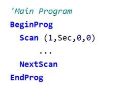
CRBasic, the CR6's full programming language, supports simple or complex programming and many on-board data reduction processes. The CR6 is compatible with CRBasic (version 3.5 or higher).
Specifications
| -NOTE- |
|
| Operating Temperature Range |
|
| Maximum Scan Rate | 1000 Hz |
| Case Material | High-impact-resistant polycarbonate and UV-resistant TPE, recycle code 7 |
| Analog Inputs | Up to 12 single-ended or 6 differential (The CR6 has 12 universal [U] and 4 control [C] terminals that can be programmed for a variety of functions. The number of analog inputs, switched excitations, and digital ports assume all the ports are configured the same.) |
| Universal Inputs | 12 individually configured inputs for analog or digital functions |
| Pulse Counters | 16 (C1 to C4 and U1 to U12) |
| Communications Ports |
|
| Data Storage Ports | microSD |
| Switched 12 Volt | 2 terminals |
| Digital I/O | 16 terminals (C1 to C4, U1 to U12) configurable for digital input and output. Terminals are configurable in pairs for 5 V or 3.3 V logic for some functions. |
| Input Limits | ±5 V |
| Analog Voltage Accuracy |
|
| ADC | 24-bit |
| Charge Terminal Characteristics (CHG+ and CHG-) |
|
| Battery Terminal Characteristics (BAT+ and BAT-) |
|
| Real-Time Clock Accuracy | ±3 min. per year (optional GPS correction to ±10 µs) |
| Internet Protocols | Ethernet, PPP, RNDIS, ICMP/Ping, Auto-IP (APIPA), IPv4, IPv6, UDP, TCP, TLS (v1.2), DNS, DHCP, SLAAC, Telnet, HTTP(S), SFTP, FTP(S), POP3/TLS, NTP, SMTP/TLS, SNMPv3, CS I/O IP, MQTT |
| Communications Protocols | CPI, PakBus, SDM, SDI-12, Modbus, TCP, DNP3, UDP, NTCIP, NMEA 0183, I2C, SPI, and others |
| Battery-backed SRAM for CPU Usage & Final Storage | 4 MB |
| Data Storage | 4 MB SRAM + 72 MB flash (Storage expansion of up to 16 GB with removable microSD flash memory card.) |
| Idle Current Drain, Average |
|
| Active Current Drain, Average |
|
| Static Vibrating Wire Measurements | Supported |
| Dimensions |
21.0 x 10.2 x 5.6 cm (8.3 x 4.0 x 2.2 in.) Additional clearance required for cables and leads. |
| Weight | 0.42 to 0.52 kg (0.92 to 1.15 lb) depending on communication option selected |
CR6-RF407 Option |
|
| Radio Type | Frequency Hopping Spread Spectrum (FHSS) |
| Output Power | 5 to 250 mW (user-selectable) |
| Frequency | 902 to 928 MHz (US, Canada) |
| RF Data Rate | 200 kbps |
| Receive Sensitivity | -101 dBm |
| Antenna Connector | RPSMA (External antenna required; see www.campbellsci.com/order/rf407 for Campbell Scientific antennas.) |
| Idle Current Drain, Average | 12 mA (@ 12 Vdc) |
| Active Current Drain, Average | < 80 mA (@ 12 Vdc) |
CR6-RF412 Option |
|
| Radio Type | Frequency Hopping Spread Spectrum (FHSS) |
| Output Power | 5 to 250 mW (user-selectable) |
| Frequency | 915 to 928 MHz (Australia, New Zealand) |
| RF Data Rate | 200 kbps |
| Receive Sensitivity | -101 dBm |
| Antenna Connector | RPSMA (External antenna required; see www.campbellsci.com/order/rf412 for Campbell Scientific antennas.) |
| Idle Current Drain, Average | 12 mA (@ 12 Vdc) |
| Active Current Drain, Average | < 80 mA (@ 12 Vdc) |
CR6-RF422 Option |
|
| Radio Type | 868 MHz SRD 860 with listen-before-talk (LBT) and adaptive-frequency-agility (AFA) |
| Output Power | 2 to 25 mW (user-selectable) |
| Frequency | 863 to 870 MHz (UK and EU) |
| RF Data Rate | 10 kbps |
| Receive Sensitivity | -106 dBm |
| Antenna Connector | RPSMA (External antenna required; see www.campbellsci.com/order/rf422 for Campbell Scientific antennas.) |
| Idle Current Drain, Average | 9.5 mA |
| Active Current Drain, Average | 20 mA |
CR6-RF427 Option |
|
| Radio Type | Frequency Hopping Spread Spectrum (FHSS) |
| Output Power | 5 to 250 mW (user-selectable) |
| Frequency | 902 to 907.5 MHz/915 to 928 MHz (Brazil) |
| RF Data Rate | 200 kbps |
| Receive Sensitivity | –101 dBm |
| Antenna Connector | RPSMA (External antenna required.) |
| Idle Current Drain, Average | 12 mA (@ 12 Vdc) |
| Active Current Drain, Average | < 80 mA (@ 12 Vdc) |
CR6-RF452 Option |
|
| Radio Type | Frequency Hopping Spread Spectrum (FHSS) |
| Output Power | 10 to 1,000 mW (user-selectable) |
| Frequency | 902 to 928 MHz |
| RF Data Rate | 115.2 or 153.6 kbps (selectable speeds) |
| Receiver Sensitivity |
|
| RF Connector | Reverse Polarity SMA (RPSMA) jack (external antenna required) |
| Idle Current Drain, Average | 15 mA (@ 12 Vdc) |
| Active Current Drain, Average | 650 mA (@ 12 Vdc) |
CR6-WIFI Option |
|
| Operational Modes | Client or Access Point |
| Operating Frequency | 2.4 GHz, 20 MHz bandwidth |
| Antenna Connector | RPSMA |
| Antenna | pn 16005 unity gain (0 dBd), 1/2 wave whip, omnidirectional with articulating knuckle joint for vertical or horizontal orientation |
| Transmit Power | 7 to 18 dBm (5 to 63 mW) |
Documents
Brochures
Manuals
Technical Papers
Compliance
- CR6 and 33205 EU Declaration of Conformity
- CR6 and 33205 UK Declaration of Conformity
- CR6-RF407 FCC Supplier Declaration of Conformity and FCC Statement
- CR6-RF422 EU Declaration of Conformity
- CR6-RF422 UK Declaration of Conformity
- RF427 Brazilian Certificate of Conformity
- CR6-WIFI EU Declaration of Conformity
- CR6-WIFI UK Declaration of Conformity
- CR6-WIFI FCC Supplier Declaration of Conformity and FCC Statement
Miscellaneous
Videos & Tutorials
Downloads
CR6 Web Browser Interface v.1.2 (801 KB) 09-13-2024
Standard Datalogger Web Browser Interface
Use this download to update the dataloggers web browser interface.
To install this file, send it to the datalogger using file control found in the Device Configuration Utility or file control found in LoggerNet.
This interface is recommended for fast IP interfaces like Ethernet and WiFi. It does NOT perform well over slow communications mediums like cellular.
Note: This is NOT for system dataloggers that have custom interfaces like the SunSentry, Hydro-Link, Alert205, and MeteoPV.
CR6 OS v.14.2.1 (8.73 MB) 04-07-2025
This download is for the CR6 datalogger. Execution of this download places the current CR6 Operating System file(.obj) and WiFi, RF45x and RF4xx operating systems (iobj) on your computer. It also updates the CRBasic Editor compiler and support files.
Why Update? New features and bug fixes. With this OS update it is recommended that you also update the Device Configuration Utility to the most recent version so that new datalogger features are available in the utility.
Note: Campbell Scientific always recommends updating operating systems on site if possible. When remote updates are required, it is recommended that you implement the necessary precautions to handle unexpected OS upload complications. All datalogger settings should be retained when updated remotely. If you choose to roll back to a previous operating system, the datalogger settings will be reset to default.
Watch the Video Tutorial: Sending an OS to a Local Datalogger.
CR6 RF45x OS Update v.4.01 (438 KB) 11-19-2024
This CR6-RF45x Series OS update is for the following:
- CR6-RF451
- CR6-RF452
Use the Device Configuration Utility to perform this update.
Device Configuration Utility v.2.32.01 (47.7 MB) 04-15-2025
A software utility used to download operating systems and set up Campbell Scientific hardware. Also will update PakBus Graph and the Network Planner if they have been installed previously by another Campbell Scientific software package.
Supported Operating Systems:
Windows 11 or 10 (Both 32 and 64 bit)
CR6 RF407 Series OS Update v.2.0 (430 KB) 07-03-2019
This CR6-RF407 Series OS update is for the following:
- CR6-RF407
- CR6-RF412
- CR6-RF422
- CR6-RF427
Use the Device Configuration Utility to perform this update.
Note: This is not for the CR6-RF451.
CR6 Wifi OS Update v.5.03 (2.23 MB) 05-21-2021
CR6 Wi-Fi OS update. This download includes the OS and the update procedure.
CPI Calculator v.1.0 (2.49 MB) 07-06-2016
The CPI Calculator is a downloadable Microsoft Excel spreadsheet used to estimate the usage and capacity of a CPI network. The calculator provides an overview on CPI devices including the CDM-A108, CDM-A116, CDM-VW300, CDM-VW305, and the CSAT3B. The calculator can also estimate the measurement speed of the CDM-A108 and CDM-A116 based on the number of channels and measurement parameters.
The CPI Calculator is an estimation tool and will help you better understand and design CPI networks by considering the following:
- What is the capability of each CDM or CPI device
- What is the CPI network capacity
- How much of the CPI capacity are the CDMs or CPI devices using
Custom Menu Example Program for Connections Video v.1 (1 KB) 03-26-2024
This program demonstrates creating a custom menu for data logger displays and corresponds to the Campbell Connections video: Creating Custom Menus in CRBasic for a Data Logger Display.
Data Logger Wiring Excel Template (1 KB) 03-26-2024
This is a data logger wiring diagram spreadsheet template that accompanies the Wiring Diagram Video. The spreadsheet includes templates for CR6, CR1000X, CR300, CR310, and CR350 data loggers. The file is an Excel template and works best with Microsoft Excel.
Frequently Asked Questions
Number of FAQs related to CR6: 9
Expand AllCollapse All
-
The CR6 has true RS-232 levels on the RJ45 (CPI), and the data logger can be programmed for RS-232 levels on C1-C2 and C3-C4.
-
When idle, the CR1000, CR6, and CR1000X consume less than 1 mA @ 12Vdc. Similar to the CR6, the CR1000X has a much faster processor that requires more power when up and running. As such, there will be higher current draws during active measurements, serial communications, or when plugged into a PC via USB or Ethernet.
It may be helpful to think of the CR6 and CR1000X as being built on the same "platform."
-
Yes. The communications tasks run independently of each other, and multiple computers can be connected at the same time. If PakBus is being used to communicate, ensure that the computers are using different PakBus addresses to communicate to the data logger.
-
The serial modem can be connected to a CR6 using any of the following methods:
- Connect the modem to the RS-232/CPI port on the CR6 using cable pn 31055 (RS-232/CPI RJ45 to DB9 Pin [Male] DTE).
- Connect the modem to the RS-232/CPI port on the CR6 using cable pn 31056 (RS-232/CPI RJ45 to DB9 Socket [Female] DCE).
- Connect the modem to a C or U terminal pair on the CR6, where the pair has been configured for serial I/O.
- Connect the modem to the CS I/O port on the CR6 using an SC105.
-
If a CPI-enabled device is running and there are skipped scans in the data logger, what can be done?
The default CPI bus speed setting is 250 kB/s. The speed is adjustable in your CRBasic data logger program. Use the CPISpeed() instruction in your CRBasic program to adjust the CPI bus bandwidth to meet the following maximum combined (total) Ethernet cable lengths:
- 1000 kB/s for maximum combined Ethernet cable lengths of 15.2 m (50.0 ft)
- 500 kB/s for maximum combined Ethernet cable lengths of 61.0 m (200.0 ft)
- 250 kB/s for maximum combined Ethernet cable lengths of 152.4 m (500.0 ft)
-
The potential transformer and the current transformer provide differential outputs that have galvanic isolation from the voltage and current in the circuit they are measuring. However, there is no need to run the outputs of these transformers into differential inputs of the data logger and unnecessarily consume additional data logger channels. We conducted extensive testing for noise immunity, for inaccuracies from ground loops, and more before concluding that single-ended measurements in the ACPower() instruction have the same performance as differential measurements would provide. Please note that as a result of the galvanic isolation of the potential transformer and current transformer, the data logger ground is NOT connected to the ground of the circuit they are measuring.
Said differently, you can connect differential outputs of a sensor to single-ended inputs of the data logger. However, doing so creates the possibility of poor common-mode noise rejection in the data logger and the possibility of introducing inaccuracies from ground loops between the sensor and the data logger. Note that in this application, the transformer isolation of the potential transformer and the current transformer eliminates these concerns.
Simply connect one of the potential transformer secondary wires and one of the current transformer secondary wires to the data logger ground. Which wire in either case makes a difference, as the phase information allows the measurement of power flowing in either direction. If you measure negative real power when it should be positive, then reverse the secondary wires of the potential transformer where they connect to the data logger. Alternatively, you can reverse the secondary wires on the current transformer, but don't reverse both pairs of wires.
-
Campbell Scientific sells, and embeds in their products, microSD cards that have single-level cell (SLC) memory. In contrast, many electronics retailers sell microSD cards that have multi-level cell (MLC) memory. The difference between these two types of memory is significant.
- The SLC microSD cards from Campbell Scientific are better suited for industrial and environmental applications where wide operating temperatures, low power consumption, and longevity are very important. Most SLC memory cards are designed with industrial applications in mind and, therefore, often have additional perks such as enhanced protection from ESD (electrostatic discharge) and mechanical damage.
- The MLC microSD cards commonly available at electronics retailers are less expensive, but they are generally not well suited for the majority of applications in which Campbell Scientific data acquisition products are used.
-
A practical maximum is to connect one multiplexer per every two control terminals on the data logger. Control terminals can be shared between multiplexers to increase the number of connected multiplexers. Sharing terminals, however, requires more complex wiring and programming. Users who would like to connect more than one multiplexer per every two control terminals are advised to contact a sales or support engineer at Campbell Scientific for assistance.
Case Studies
The Expressway S19 represents a critical link in Europe’s transportation network, stretching 570 km (354.2......read more
Understanding the spatial variability of the Earth’s atmospheric boundary layer—including the surface layer near the......read more
Overview The reconstruction of the navigational lock system at the Iron Gate I Hydroelectric Power Station......read more
The Homestake Neutrino Experiment—also referred to as the “Davis Experiment” after physicist Ray Davis, who......read more
In the intricacies of transportation networks, bridges take center stage, knitting together communities and ensuring......read more
Background Think of the First Transcontinental Railroad. Minor errors in surveys and maps could have led......read more
Background Tailings dams are crucial components of mining operations, responsible for storing water used in the......read more
Levees are used in every state in the US with a higher concentration in states......read more
Articles and Press Releases
Blog Articles
-
How do you know if your CR6 is maxed out?

02-18-2025 Author: Eric Schmidt -
Behind the Scenes: Scientifically Adding Some Jingle to the Holidays

12-17-2024 Author: Eric Schmidt -
Open the Door to Unlock Flexibility

08-20-2024 Author: Eric Schmidt -
How to Optimize Your Data Acquisition

07-02-2024 Author: Michael Adams -
How to Enhance Your Data-Acquisition Capabilities

06-18-2024 Author: Michael Adams -
How to Achieve Unmatched Vibrating Wire Speeds

06-04-2024 Author: Michael Adams -
Putting People First: Crafting Cost-Effective Solutions with Campbell Scientific

05-07-2024 Author: Michael Adams -
A Deeper Look: Our Role in the Hole

04-23-2024 Author: Michael Adams -
A Closer Look: Resolving Dam Data Discrepancies

03-05-2024 Author: Eric Schmidt -
Why Is the CR6 the Preferred Automated Monitoring Platform for Geotechnical Applications Worldwide?

01-08-2024 Author: Michael Adams -
Get the Most out of VSPECT®

08-22-2023 Author: Jacqalyn Maughan -
Use VSPECT® to Verify: Bad Sensors or Bad Data?

04-06-2023 Author: Jacqalyn Maughan -
Troubleshooting Vibrating Wire Piezometers

03-28-2023 Author: Nathanael Wright -
How to Generate SFTP Keys Easily

09-12-2022 Author: Nathanael Wright -
What You Should Know: Improvements to SMSSend()

04-09-2021 Author: Dana Worley -
How to Obtain Vibrating Wire Measurements in Environments with High Electromagnetic Noise

10-07-2020 Author: Timothy Jeppsen -
It’s Time to Embrace the Hybrid

12-02-2019 Author: Kevin Rhodes -
How to Monitor Your Campbell Cellular Modem Data Usage: Part 1

01-16-2019 Author: Nathanael Wright -
Edlog Data Logger Support and You

12-05-2018 Author: Jacob Davis -
New Product Support: Kipp & Zonen’s RaZON+

01-17-2018 Author: Matt Perry -
Get Answers to Your Data Logger Questions Quickly

01-04-2018 Author: Michelle Welch -
How Safe Are Your Campbell Scientific Devices from KRACK?

10-18-2017 Author: Jacob Davis -
New Ethernet over USB Functionality for Data Loggers

08-30-2017 Author: Dana Worley -
A Quick Comparison of the CR1000X, CR1000, and CR6 Dataloggers

08-16-2017 Author: Timothy Jeppsen -
The CR1000X: A New Generation of Data Loggers with Proven Functionality

08-02-2017 Author: Timothy Jeppsen -
Sending Email from Your Data Logger Just Got Easier!

01-25-2017 Author: Dana Worley -
Available Security Measures for Internet-Connected Data Loggers

12-07-2016 Author: Dana Worley -
Sharing Your Monitored Data via Social Media

10-28-2016 Author: Barbra Utley -
The Internet of Things (IoT) – Doing Our “Thing” Since Y2K

09-28-2016 Author: Dana Worley -
5 Steps to Post Your CR6 Data to Weather Underground

03-23-2016 Author: Sam Utley
Newsletter Articles
- Coming Soon: New CPEC300-Series Closed-Path Eddy-Covariance Systems 01-24-2018
- CR6 Upgrade 11-15-2017
- New Communication Options for Our CR6 and CR300 Dataloggers 01-16-2017
- New Radio Options for CR300 and CR6 Dataloggers 10-28-2016
- Case Study: Buoy System in Costa Rica 07-21-2016
- Case Study: Hydro-SCADA System in Northern California 04-18-2016
- CR6-RF451 Available Soon 04-18-2016
- CR6 Now Has Wi-Fi Option 02-02-2016
- New Operating System for the CR6 10-15-2015
- Novel Application of Measurement and Control Capabilities of CR6 10-15-2015
- New CR6 Datalogger 10-20-2014
Privacy Policy Update
We've updated our privacy policy. Learn More
Cookie Consent
Update your cookie preferences. Update Cookie Preferences


