Preprogrammed and low power


Overview
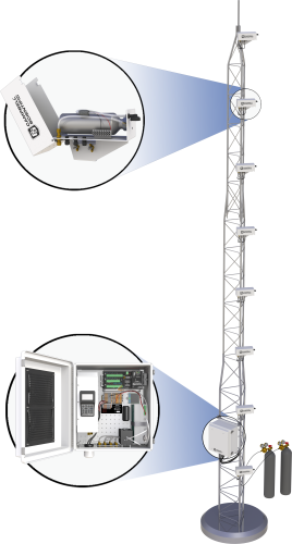
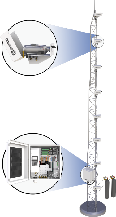
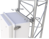
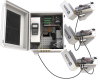
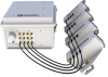
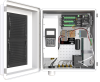
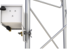
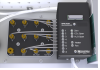
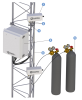
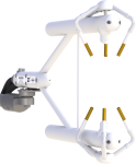
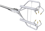
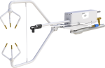
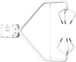
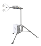
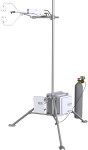
The AP200 is a complete, integrated CO2 and H2O atmospheric profile system. It measures carbon dioxide (CO2) and water vapor (H2O) concentration from up to eight intakes, which are normally spaced along the height of a tower to give a vertical profile. The AP200 is often used in conjunction with an eddy-covariance system to measure the storage term and provide you with a more complete measure of the surface gas exchange.
Read MoreBenefits and Features
- Fully integrated system
- Requires only 13 W (average at 25°C and 12 Vdc)
- Contains a Campbell Scientific CR1000X Measurement and Control Datalogger
- Automatically performs CO2 zero and span
- Automated temperature and pressure control
- Data logger program included
Images


Similar Products
Detailed Description
Measurements
Primary:
- CO2 concentration at each intake
- H2O concentration at each intake
- System diagnostic word
Secondary:
- Sample flow rate
- Sample cell pressure
- Sample cell temperature
- Other control variables
Note: Contact the Micromet Group at Campbell Scientific for questions or updates regarding the data logger program.
Specifications
System Enclosure |
|
| Operating Temperature | -30° to +45°C |
| Power Requirements |
|
| Dimensions | 52.1 x 44.5 x 29.7 cm (20.5 x 17.5 x 11.7 in.) |
| Weight |
|
Pump Module |
|
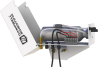
| Pump Type | Dual-head diaphragm pump with a brushless dc motor |
| Mounting | Mounted in an insulated, temperature-controlled box inside system enclosure |
| Control | Pumping speed is automatically controlled to maintain the pump inlet pressure at the set point |
| Maximum Pumping Speed | 9.0 liters per minute (LPM) |
| Pressure Sensor Range | 15.0 to 115.0 kPa |
| Heater | 8.0 W (turns on/off at 2°C) |
| Warm-up Time | ~50 min (from -30° to +2°C) |
| Fan | 0.7 W (turns on at 50°C and off at 45°C) |
Valve Manifold |
|
| Mounting | Mounted inside system enclosure |
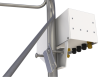
| Inlets | Eight air sample inlets plus one inlet for zero, one inlet for CO2 span, and one inlet for H2O span |
| Connections | 0.25-in Swagelok |
| Mass Flow Sensor | 0 to 1.0 standard liters per minute (SLPM) |
| Heater | 8.0 W (turns on/off at 5°C) |
| Warm-up Time | ~20 min (from -30° to +4°C) |
| Fan | 0.7 W (turns on at 45°C and off at 43°C) |
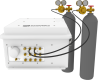
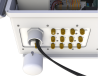
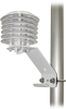
Intake Assembly |
|
| Filter | 1.0-in diameter, sintered stainless-steel disk filter, 10-micron pore size |
| Orifice Heater | 2 kohm (0.07 W at 12 Vdc) |
| Mixing Volume | 750 mL |
| Sample Connection | 0.25 in. Swagelok |
| Number of Connections for Heater Cable Entry Seals | 3 (1 in, 2 out) |
| Cable Diameter for Heater Cable Entry Seals | 2.8 to 6.6 mm (0.11 to 0.26 in.) |
| Wire Diameter for Heater Cable Screw Terminals | 26 to 12 AWG |
| Wire Stripping Length for Heater Cable Screw Terminals | 5.0 mm (0.2 in.) |
| Screw Tightening Torque for Heater Cable Screw Terminals | 0.4 N•m |
| Orifice Inside Diameter | 0.178 mm (0.007 in.) |
| Dimensions | 31 x 12.5 x 19 cm (12 x 5 x 7.5 in.) |
| Weight | 1.4 kg (3.1 lb) |
Documents
Brochures
Miscellaneous
Downloads
AP200 CR1000 Program v.2.01 (31.3 KB) 01-12-2021
AP200 CR1000(X) Program.
Compatible with the LI-850.
Note: For those with the LI-840 contact Campbell Scientific for compatible code.
Device Configuration Utility v.2.32 (47.7 MB) 03-19-2025
A software utility used to download operating systems and set up Campbell Scientific hardware. Also will update PakBus Graph and the Network Planner if they have been installed previously by another Campbell Scientific software package.
Supported Operating Systems:
Windows 11 or 10 (Both 32 and 64 bit)
Frequently Asked Questions
Number of FAQs related to AP200: 53
Expand AllCollapse All
-
It depends on the type of chambers. The AP200 requires a constant flow of sample air for each intake, so it will not work with small chambers that require the air sample to recirculate. However, it might be possible to use the AP200 with chambers that allow a continuous sample flow to be extracted.
-
No. Because the AP200 has only eight inlets for air samples, it can only operate with a maximum of eight intake assemblies.
-
Numbering this way helps reduce the time skew between measurements of the intakes. To illustrate this, consider a parcel of air that moves through the intake tubes at approximately 0.5 m/s. If the longest tube is 60 m longer than the shortest tube, its travel time is two minutes longer than the shortest tube. Sampling from the shortest tube first means that the air samples enter each tube at the same time.
-
If the pump fails, it must be replaced. Contact Campbell Scientific for details. For the process of returning equipment to Campbell Scientific, refer to the Repair and Calibration page.
-
Yes. The AP200 can be ordered without an LI-840A so that a facility may use one it already owns. All the required mounting hardware and plumbing fittings are shipped with the AP200. The installation requires no tools and is very easy. The installation instructions are provided in the AP200 Instruction Manual. The AP200 will automatically configure the LI-840A.
-
The expected precision for the half-hour average CO2 and H2O concentrations is 0.08 ppm for CO2 and 0.0008 ppt (0.8 ppm) for H2O. This is estimated as follows. The LI-840A maximum RMS noise specification is 1 ppm for CO2 and 0.01 ppt for H2O. Assuming the AP200 is configured with eight levels, it will switch to a new level every 15 s, cycling through the set of eight levels every two minutes. Each time the valves switch, the first 10 s are omitted for equilibration, and 5 s (10 samples) are included in the average. In each half-hour averaging period, each level will have a total of 150 samples (10 samples per cycle, and 15 cycles per half hour). The precision of the CO2 and H2O average concentrations can be given as the standard error of the mean. This is calculated as the RMS noise of individual samples divided by the square root of the number of samples, giving a precision of 0.08 ppm for CO2 and 0.0008 ppt (0.8 ppm) for H2O.
-
The LI-840A does not require any routine maintenance if it is used as described in the AP200 and LI-840A manuals.
-
The filters on the intake assemblies should keep the IRGA sample cell clean for a long time. A long-term test of an AP200 outside Logan, UT, showed that the sample cell was still clean after a year of operation. However, if it becomes difficult to span the LI-840A, if there is excessive noise, or if there is excessive drift in either the CO2 or H2O zero, then it may be necessary to clean the sample cell. Refer to the instructions in the LI-840A user manual.
-
No. If the LI-840A requires repair or recalibration, return it to LI-COR.
Case Studies

This case study discusses the integration of CPEC310 and AP200 systems to explore the theories......read more

The Warra long-term ecological research (LTER) site located in Southwestern Tasmania was founded in 1995......read more
Articles and Press Releases
Newsletter Articles
Privacy Policy Update
We've updated our privacy policy. Learn More
Cookie Consent
Update your cookie preferences. Update Cookie Preferences